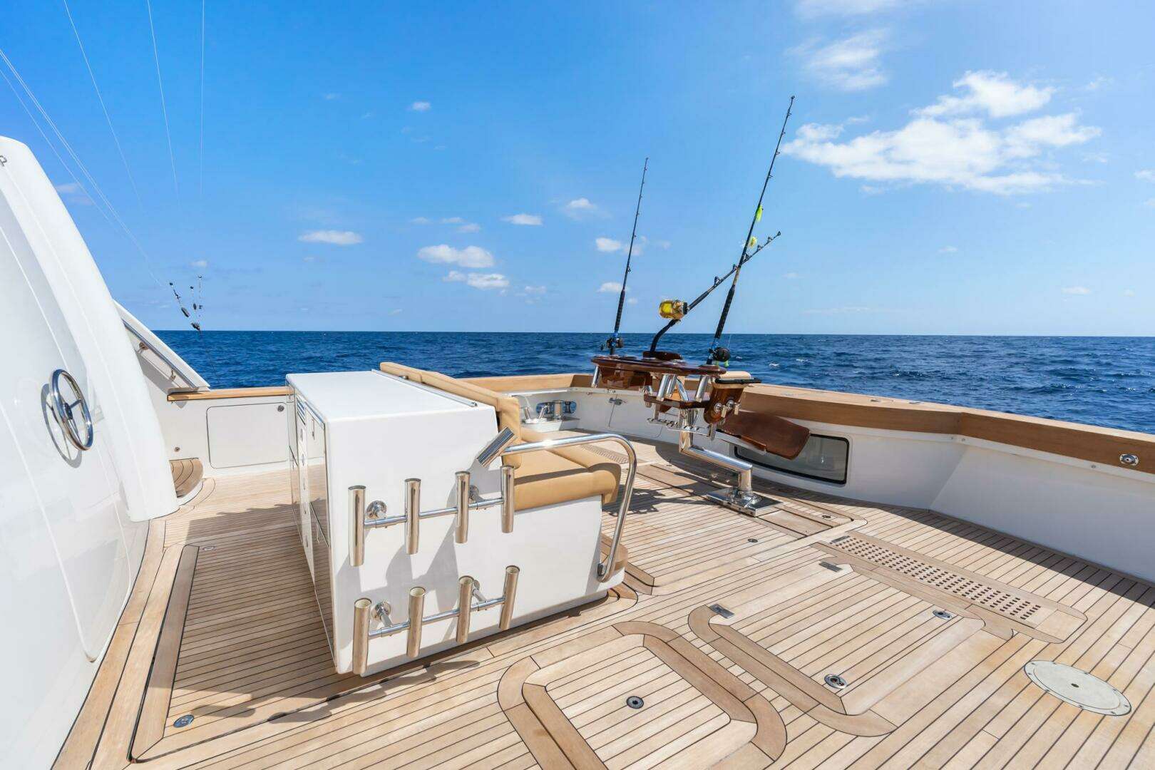
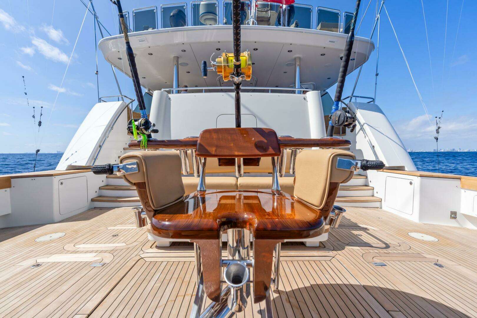
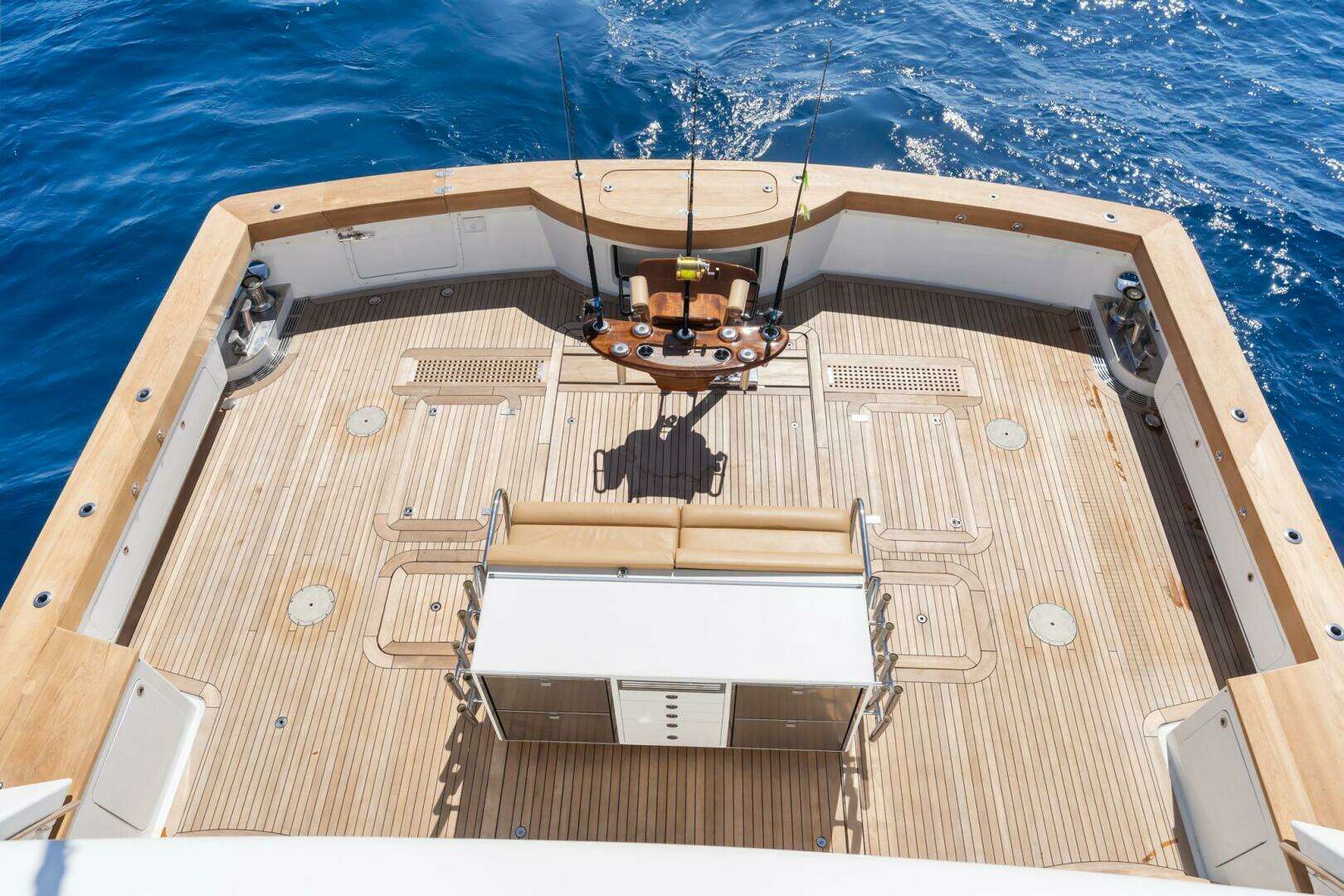
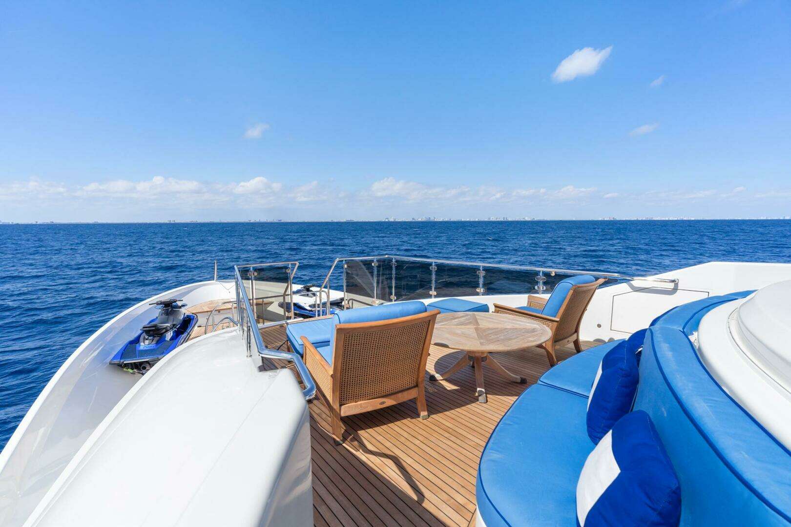
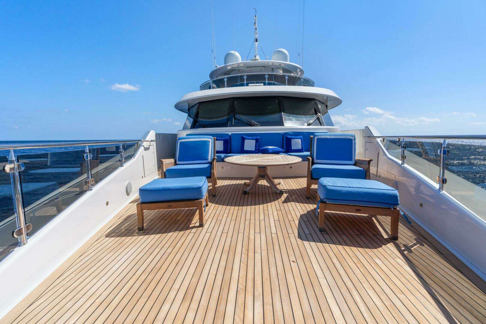
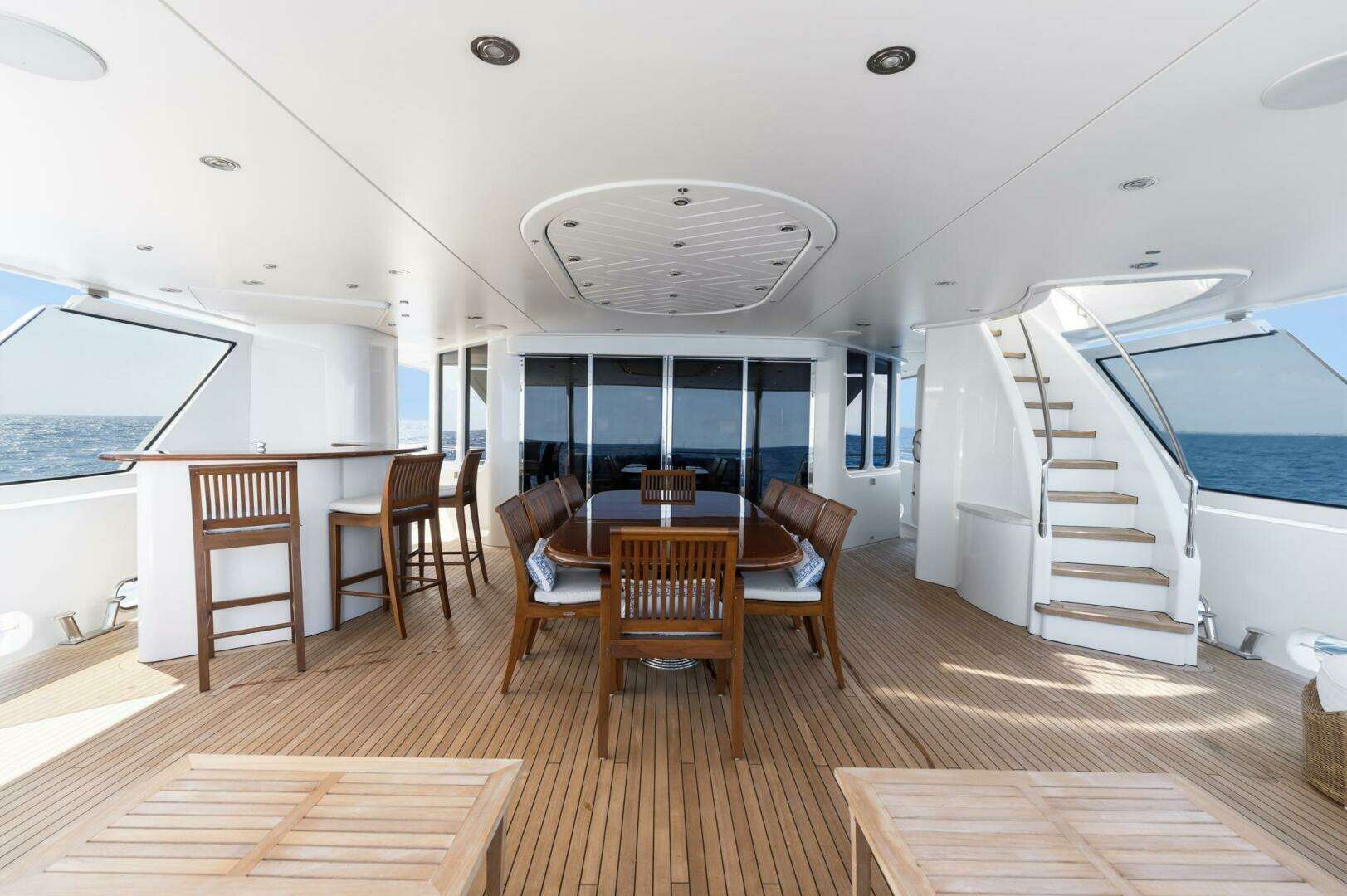
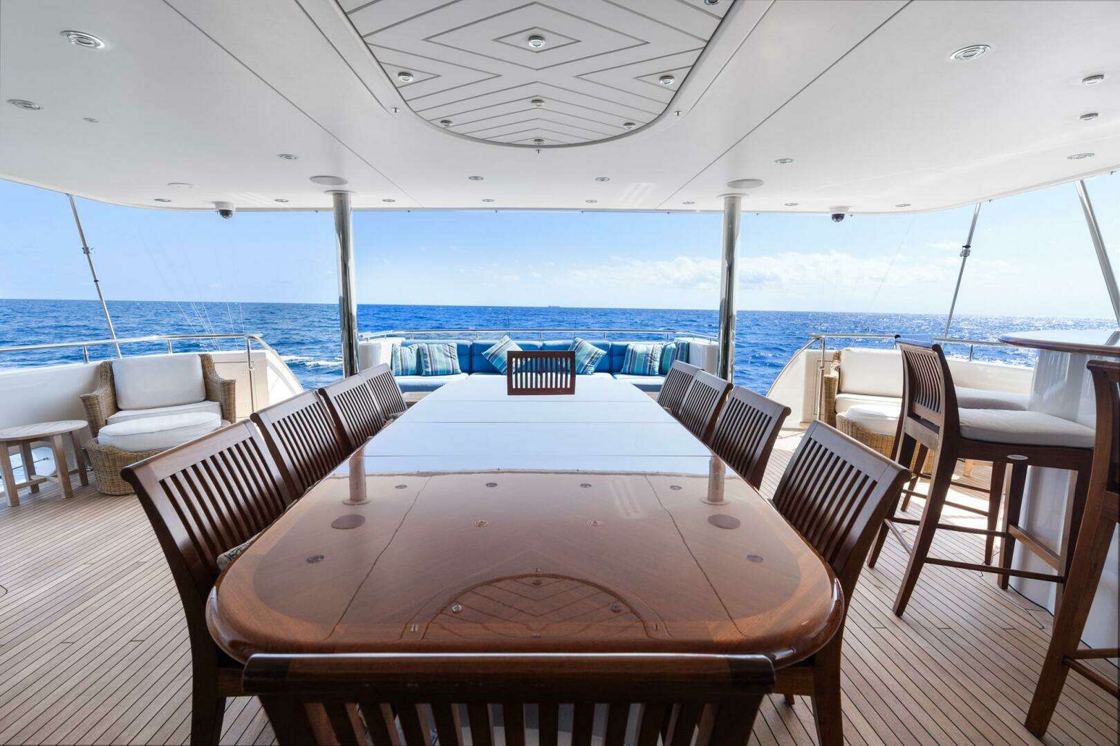
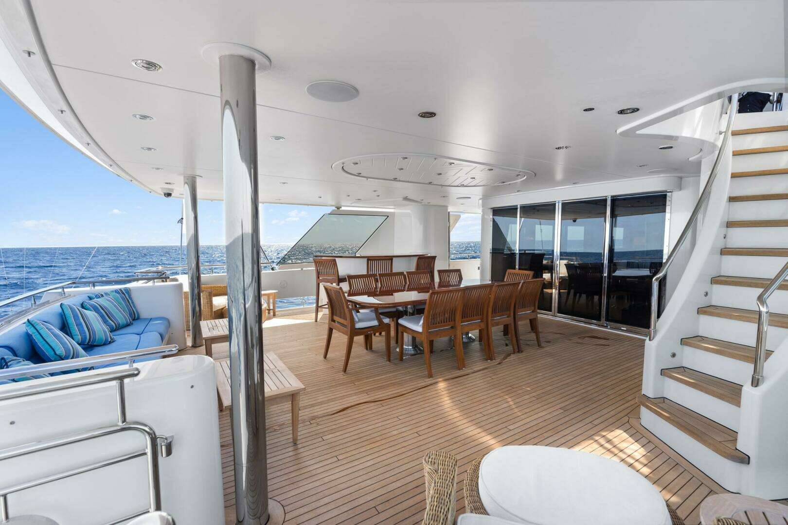
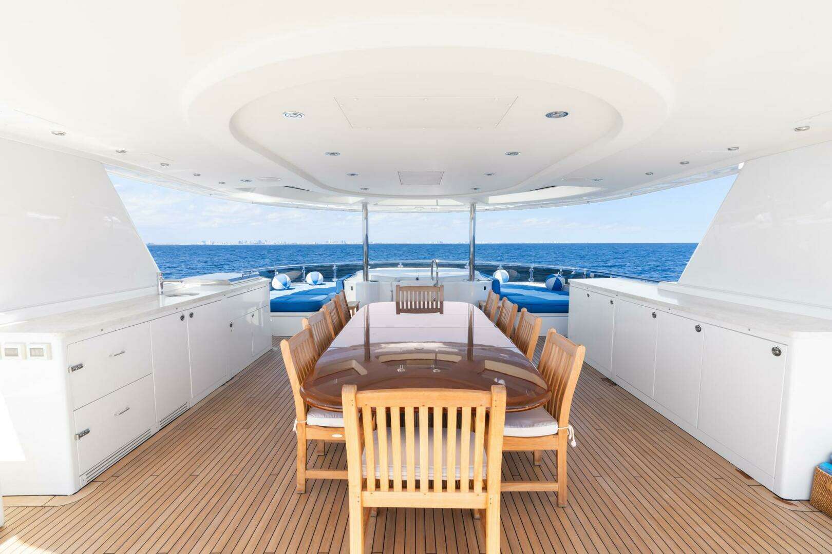
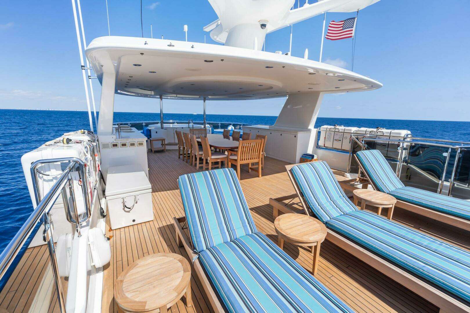
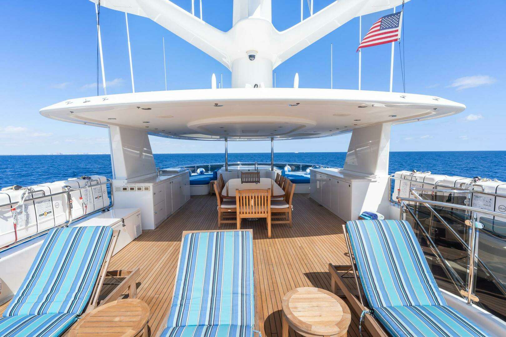
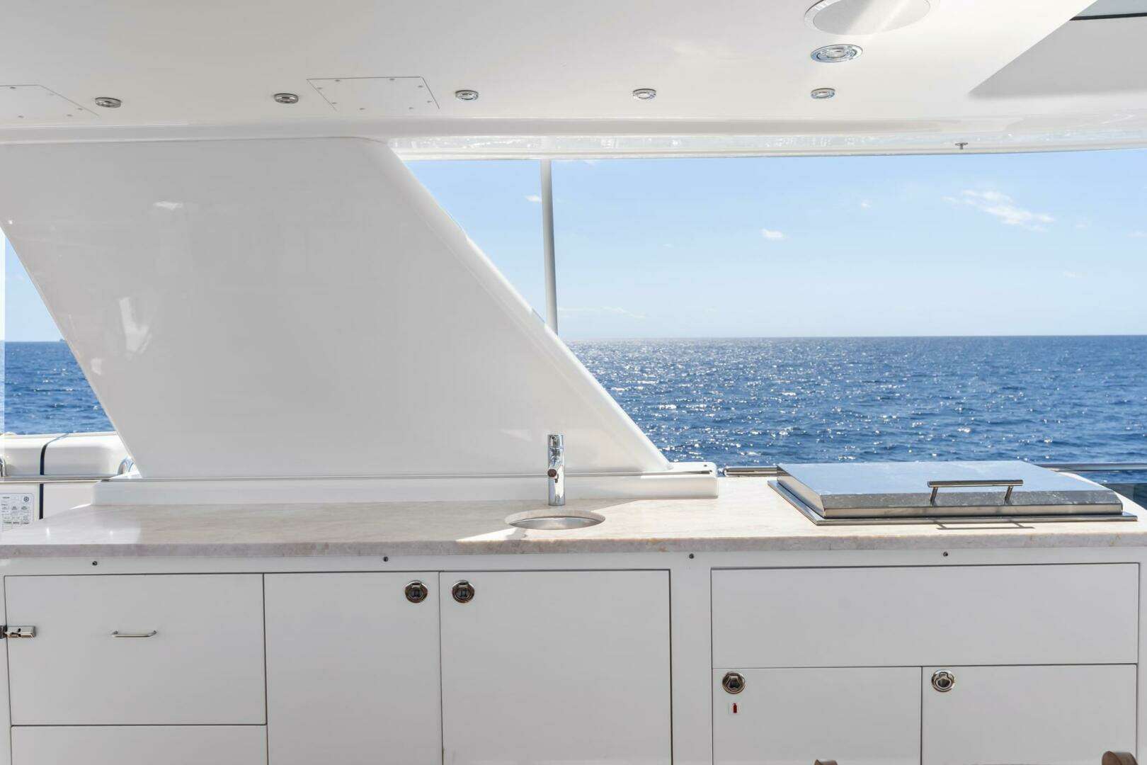
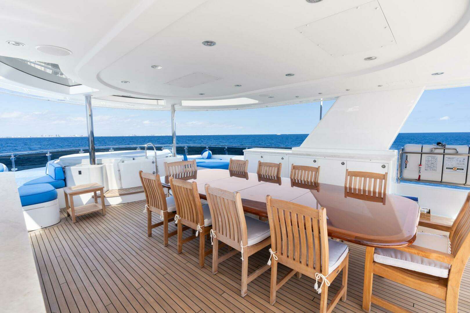
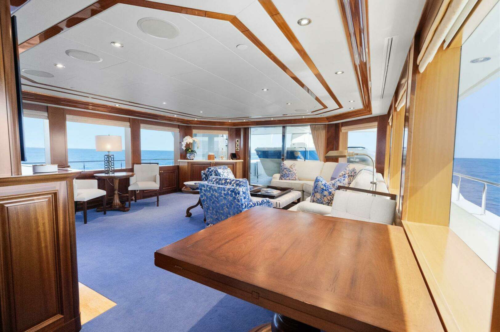
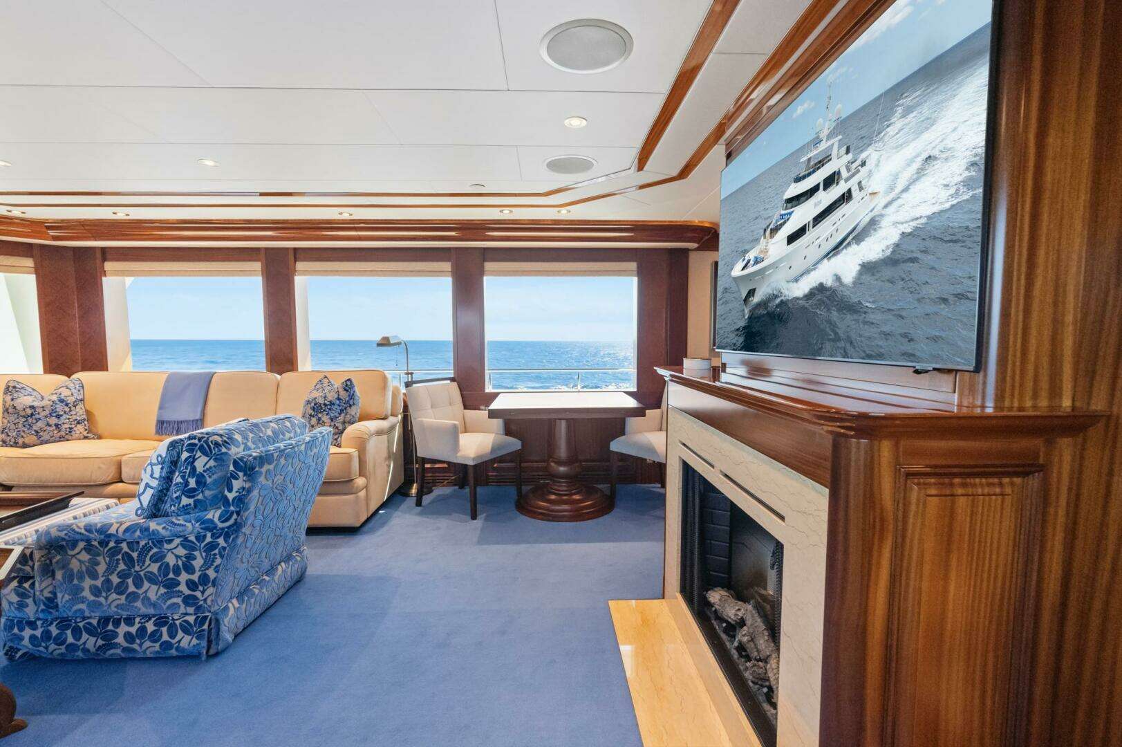
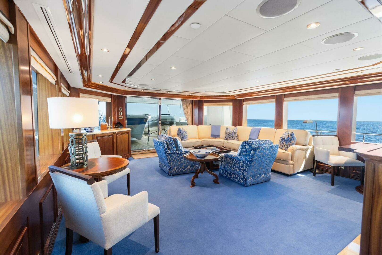
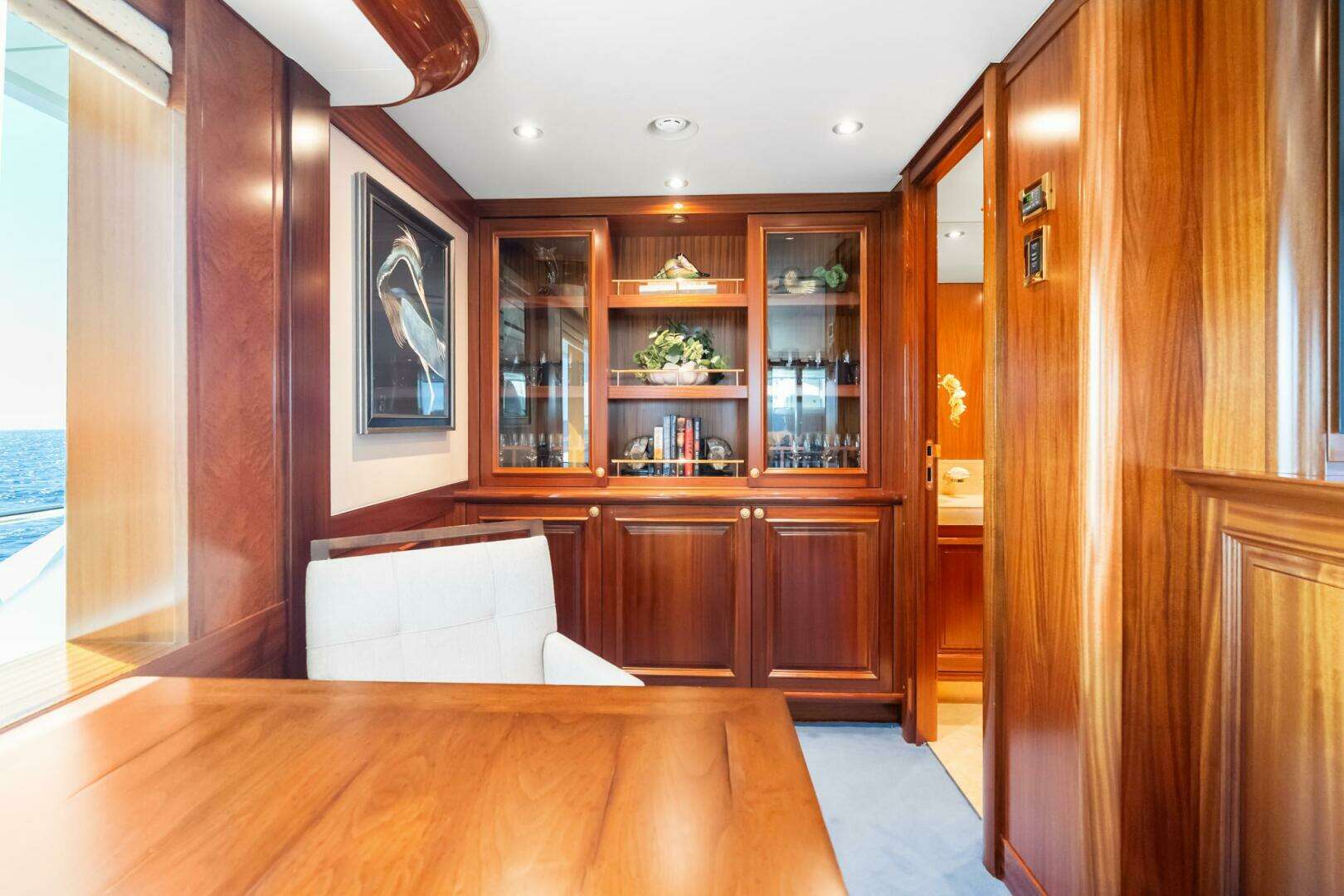
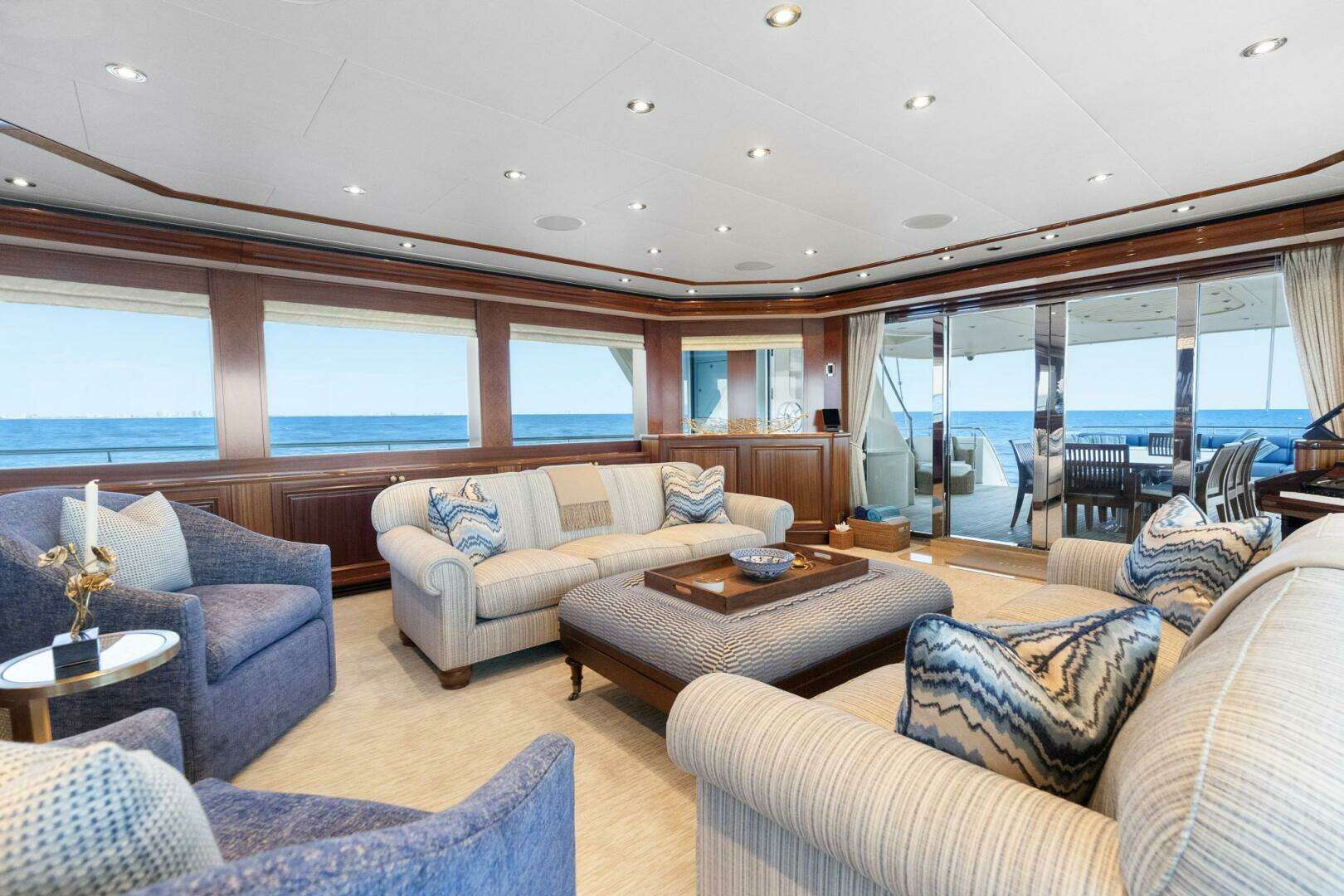
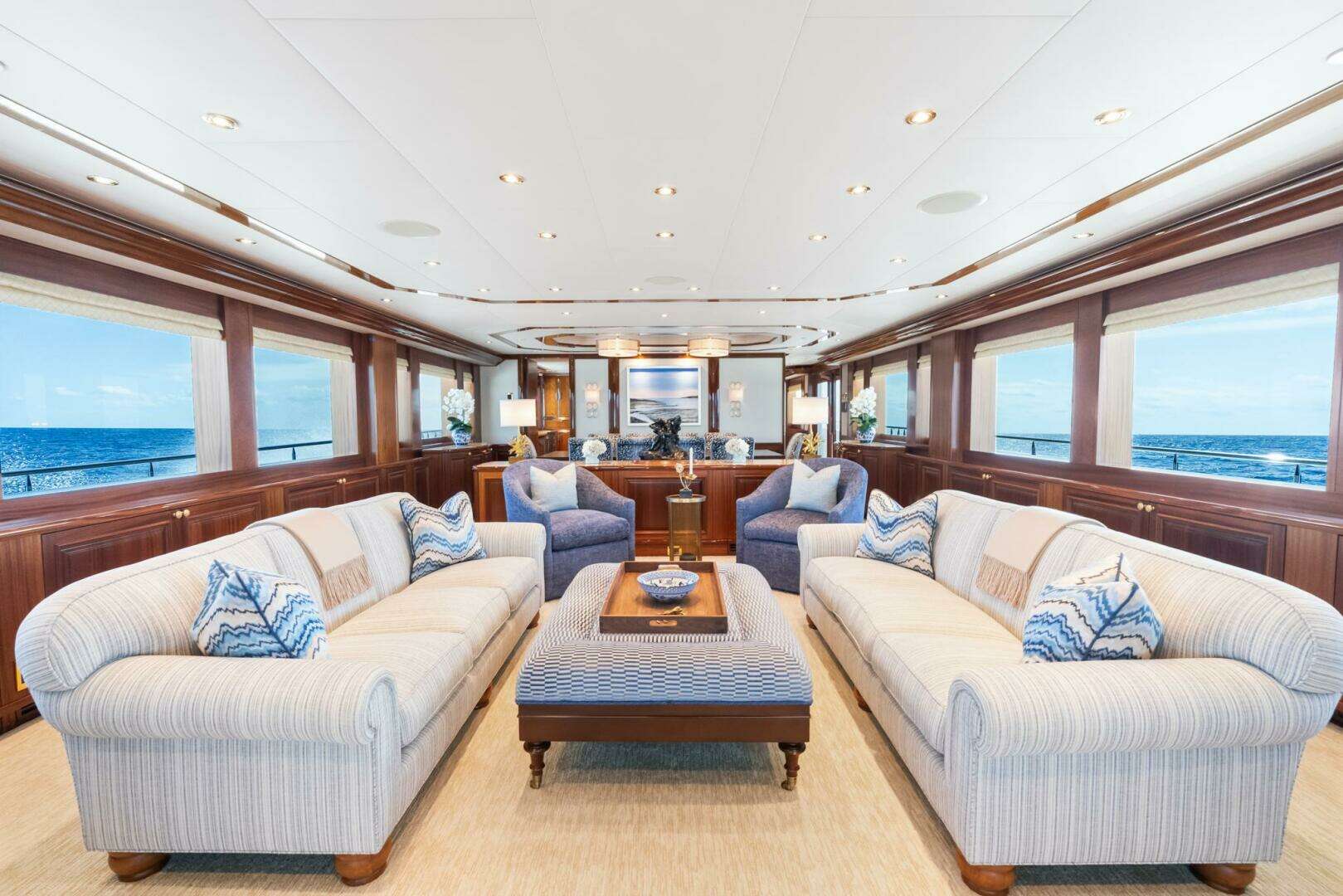
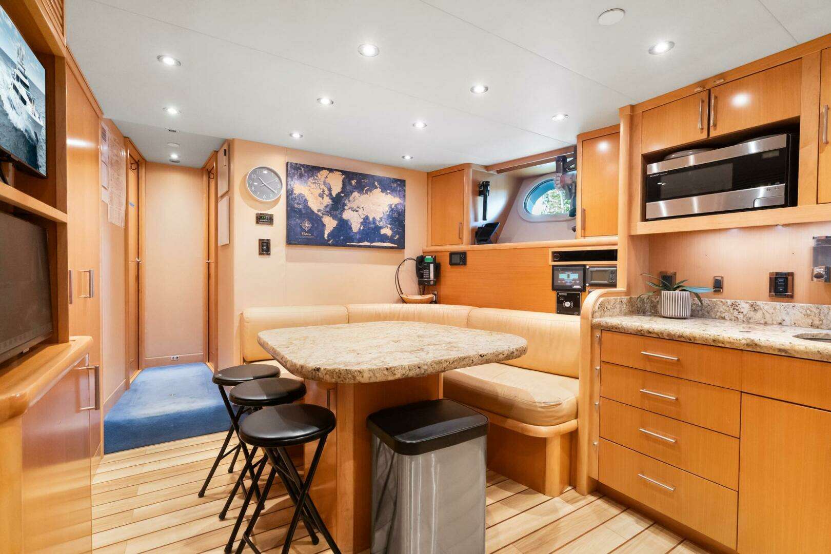
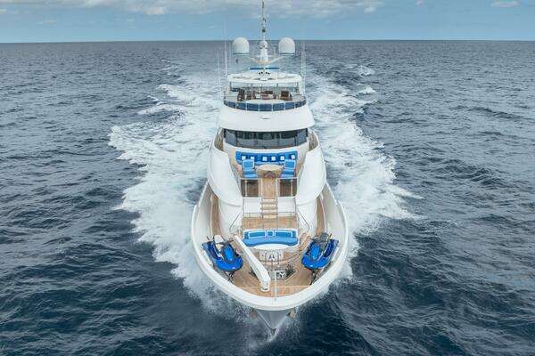
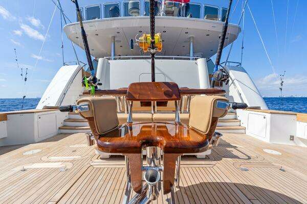
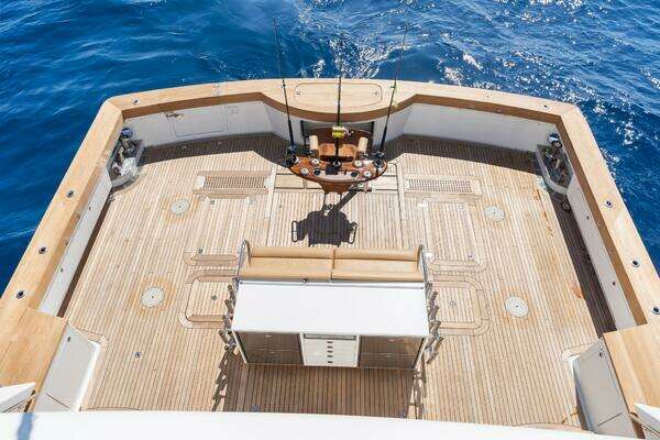
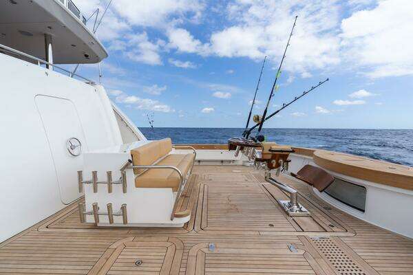
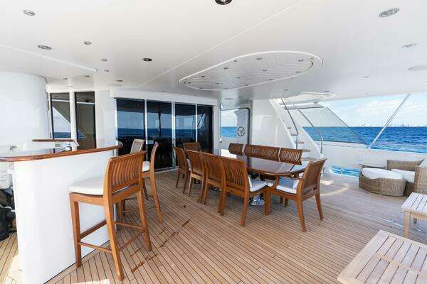
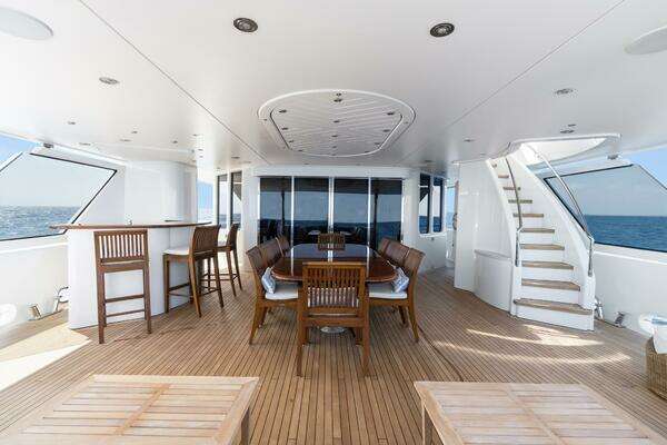
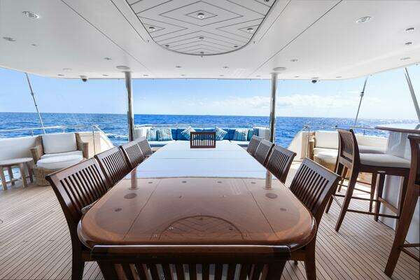
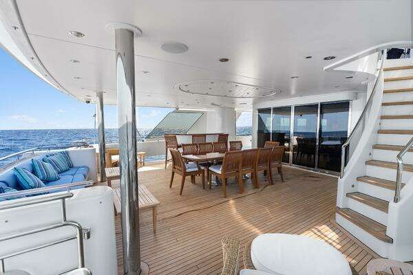
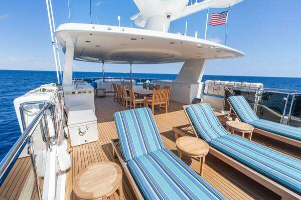
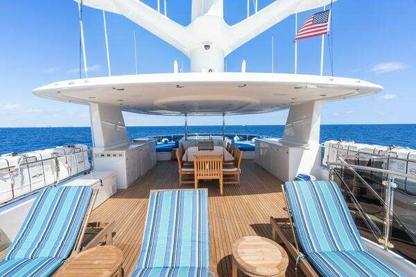
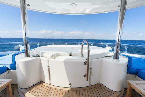
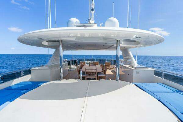
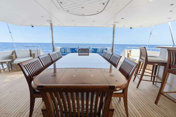
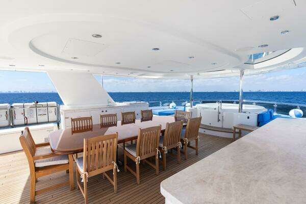
Comfortable and well-appointed exterior area for outdoor entertaining with a full-service bar, generously sized cushioned aft settee with convertible cocktail/dining teak table, four dining chairs (loose), and A/V equipment.
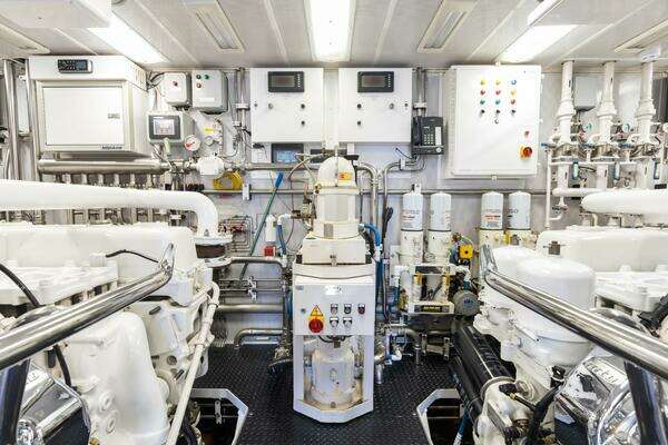
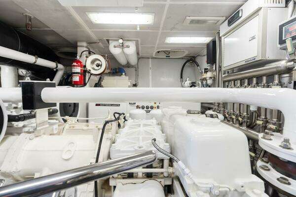
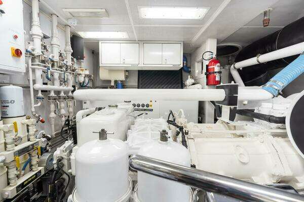
systems
FUEL SYSTEM:
Total capacity (diesel): Approx. 10,600 gal. (US) in six (9) tanks. Fueling process is via either of two deck fill locations amidships, port and starboard side. All tanks are vented to atmosphere on the starboard side. Fill/transfer system includes a centrifuge, pumps, meter and distribution manifold. All diesel consumers draw from the day tank. Engines and Generators are supplied via priming pumps and filters. During normal operations fuel is transferred to the day tank via the centrifuge. Tank level monitoring is via electronic sensor and display on Vessel Monitoring System with high/low level alarms. All tanks are vented to one ‘vent tank’ which is monitored for liquid indicating an overflow of any of the attached fuel tanks. Tanks are all aluminum, welded construction with internal baffles. Inspection access ports to be manufactured by Freeman Marine.
TANKS:
Fuel Tanks (Diesel): #1 Center Tank: approx. 643 gallons #2 Center Tank: approx. 675 gallons, #3 Center (Day Tank):approx. 1975 gallons, #4 Port and Stbd Tanks: approx. 2760 gallons, each #5 Center Tank 6 starboard cockpit 384gallons, Tank 7 starboard cockpit 419 gallons, Tank 7 port cockpit 419 gallons, gas 200 gallons port forward cockpit.
FILL/TRANSFER/USE:
Port & Starboard deck fill; threaded, SS, stamped DIESELY Strainer: 316 SS, self-cleaning Centrifuge: Alpha Laval, 198GPH (Gallons/Hour); diesel/oil separator Primary Pump: AC, 50 GPM Secondary Pump: DC positive displacement back-up/priming pump Filters: DDC SeaPro 600 Meter: Electronic turbine with numerical display and automatic pump shut off Transfer manifold by Westport Shipyard Main Engines Priming Pump: Jabsco, 24VDC, 558 GPH Filter: SeaPro 600,Dual Generators Priming Pump: Carter, 24VDC, 35 GPH Secondary Pump: DC positive displacement back-up/priming pump Filter: Racor, 500 Duplex Turbine Series
FRESH WATER SYSTEM:
The Fresh Water System is comprised of a single, divided and baffled, fresh water tank, two AC supply pumps, suction supply, service, and distribution manifolds, two reverse osmosis water makers, and associated valves, filters, expansion tanks, regulators, and gauges. Freshwater wash-downs are located on all external decks. Fresh Water Tank (Divided): Stainless steel, approx. 1726 total gallons Purification: Silver ion electrolytic water sterilization system UV filters: Two for disinfection of potable water, 29 GPM each. Water Softener: Yacht Mate DM1000 system, with Swim Platform water connection, plumbed directly to the fresh water tanks, located in the equipment room. Deck fills: Two stainless steel, 1 ½” round with threaded caps. One quick connect fitting, located on the swim step bustle is plumbed to supply the water softener. Water makers: (2) Sea Recovery Aqua-Whisper 1800. Reverse osmosis type, for a total capacity of 3600gallons per day Water Heater: Dual element (for fast recovery) water heater, 120-gallon capacity. Dual particle filters: For removal of sediment, dissolved solids and contaminants to 5 microns plumbed in parallel. Stainless steel canister with replaceable filter cartridges Pressure tank: FRP construction located at remote ends of piping system Pumps: (2) centrifugal pressure pumps, 30 gpm each, plumbed in parallel for high flow capability.
LUBE OIL SYSTEM:
The vessels’ main engines and generators can be serviced utilizing an onboard lube oil change system. A new oil tank and a used oil tank are fitted within the engine room. New oil can be filled via 1 ½” deck fitting amid on starboard side while used oil can be offloaded with quick-connect hose. Two air-powered diaphragm pumps are used to transfer to/from locations via hose reels. Lube Oil Tanks: 450-gallon total oil capacity in a divided tank, located in the Engine Room bilge area. Tank is made from5086-H32 Aluminum Lube Oil - New: 185 gallons Lube Oil - Used: 265 gallons Pump: Two (2) air diaphragm pumps. Fittings: All stainless quick connect fittings. Deck Plate: Located with midship fuel fill on starboard side.
WASTE WATER SYSTEM:
Black and gray water is routed to an FRP tank. A certified Marine Sanitation Device (MSD) is installed for treatment of all wastewater. Tank level monitoring is via electronic sensor and display Vessel Monitoring System with level alarms and all tanks are vented at boot stripe. Discharge is via MSD or direct overboard via diaphragm pump. Also, a dockside pump out connection is located port aft on the swim platform. Pumps: High-capacity solids handling AC diaphragm pump. MSD: Certified to meet MARPOL regulations as well as USCG Type II MSD. (Includes chlorine generator) Black WaterTank: FRP construction with internal baffles, approx. 1685 gal. Gray water collection/movement: Three sumps (crew, guest and engineers) for transfer to black water tank or directly overboard via Y-valve. Westport construction, include
primary AC pump and DC back-up pump with strainer, inspection port and alarm on DC pump. A lift station for the galley also acts as a sump pump, but only has an AC pump.
COMPRESSED AIR SYSTEM:
The vessel will have a compressed air system for powering the ship’s whistle, gasoline dispensing pump and oil dispensing pump, as well as for use in the machinery spaces for air powered tools. The system consists of compressor, piping system, quick connect fittings, and (3) accumulator tanks. Quick Connect Fittings: Located; FWD escape hatch, Port Swim Step, Exterior Bar (port side) on Pilothouse deck and Flybridge Mast Leg (starboard) in storage locker. Accumulator tanks: 3 -10-gallon units, 2 in the Engine Room and 1in the stbd. Flybridge mast leg storage locker. Hose/Reel: Reel Craft - Hose ½” x 35’Compressor: Kaeser 5hp SX-6
BILGE SYSTEM:
The bilge system consists of five (5) float switches for all of its watertight compartments, two AC electric bilge pumps, valve manifold, and piping with fixed strainers from each watertight compartment. Float switches will send signals to the Monitoring System when water accumulates in any of the bilge areas. The manifold allows cross over to the fire pump or diesel powered pump for back up. Pump, Primary: Centrifugal, 100gpm@10 psi Pump, Back-up: See fire main back up pump(Shared on common manifold).
DECK DRAIN SYSTEM:
All exterior decks are fitted with freeing ports and/or drains with a plumbed piping system. Deck drains are molded portions of the deck and fitted with polished stainless-steel grates. All drain piping is of ABS approved materials, PVC –DWV and are led to laminated thru hulls located at the boot stripe with check valves and ball valves.
FIRE HYDRANT SYSTEM:
The fire main system consists of four (4) fire stations distributed around the vessel, supply piping and two pumps. Each station contains a hose, angle valve and high/low volume nozzle. The electric fire pump (primary) can be started from any fire station or locally. Hoses (7): 1 ½” x 50’ FM listed lay flat type, NPSH thread ABS Approved Fire Nozzles: ABS Approved, one at each of (4) hydrant stations Pump, Primary: Centrifugal, flooded suction, 66gpm@40psiPump, Back-up: Diesel powered portable, flooded suction centrifugal Strainer: Sea suction strainer for fire/bilge manifold, Bronze 2” Y strainer or equivalent Seawater intake: Bronze with stainless steel grate. Westport design and supply Hose Rack: FRP construction, with rolled hose storage in fire station
FIRE SPRINKLER SYSTEM:
The accommodation space is protected by a sprinkler system that uses vessel’s fresh water supply until it is depleted, then automatically, if necessary, switches to seawater. The engine room is protected by a gas smotheringFM200 system. Sprinkler system: The system is a pre-charged type, automatic fire suppression system. The pump unit consists of two pumps, operating individually or in tandem depending on the demand for water as determined by the number of heat sensitive nozzles that have been triggered. A small pressure tank maintains the stand-by pressure in the system. A local control panel is located in the engine room and a mimic display is located in the pilothouse.
ENGINE ROOM FIRE SYSTEM:
The engine room and ventilation ducts are to be insulated against thermal conductivity meeting the A-30rating and also to provide effective sound damping. Insulation: The bulkheads and duct work leading to the engine room are lined with a thermal barrier of insulation.FM200, Gas smothering system: For engine room protection, manual operation (with 20second delay) includes discharge of gas and automated shutdown of fuel pumps, intake fans, and exhaust dampers.
GALLEY HOOD FIRE SYSTEM:
Independent, fixed system is located in the main Galley in the hood above the stove.
STABILIZATION:
Stabilization is achieved through 3 independent systems, creating a very stable and capable vessel. Originally Stabilization is provided by a pair of Naiad Model 225, 22sq foot fins located amidships and powered hydraulically by an engine driven pump. At rest stabilization is achieved by the same system and also through two independent VEEMVG5250 gyro stabilizers located below deck in the cockpit.